

 May 13, 2026


A 36V battery pack for an e-bike and a pack for an automated guided vehicle need different purchasing specifications. The voltage label alone cannot establish compatibility. Start with the controller voltage window, battery chemistry, actual duty cycle and approved charging arrangement. Then agree on the mechanical interface, protection behavior and sample evidence for the exact configuration.
This guide helps e-bike brands, equipment manufacturers and AGV integrators turn those requirements into a reviewable OEM inquiry. It separates catalogue references from proposed applications, explains useful energy and current calculations, and sets out a sample acceptance process. For enclosure options, begin with the custom battery pack range, then identify the specific configuration being offered.

Ask for nominal voltage, maximum charging voltage, discharge limits and the controller operating window on one comparison sheet. A 36V class description is a platform label, while compatibility depends on the actual electrical boundaries. A pack with a similar nominal voltage may still have a charging limit or protection behavior that the equipment cannot support.
Chemistry and series configuration help explain that distinction. As a nominal arithmetic example, twelve cells at 3.2V give 38.4V, while ten cells at 3.6V give 36V. These calculations illustrate different configurations; they do not prescribe cell selection, charger settings or operating limits. Obtain the actual cell and pack specification instead of designing from the label.
One documented reference is SMG36100 in the energy storage battery parameter table. The public table reviewed on October 24, 2026 lists 100Ah, 3,840Wh and a 12S BMS configuration. Dividing the listed energy by capacity gives a 38.4V nominal reference. Its listed enclosure is 522 × 269 × 221mm, expressed as length, width and height.
Those figures describe a catalogue entry in an energy storage range. They do not establish that SMG36100 fits an e-bike frame or is approved for an AGV. The applicable drawing, load capability, charging requirements, environment and application qualification still need confirmation. A public product table is a starting point for discussing a configuration, not a substitute for that review.
Include startup, low energy shutdown and recovery in the voltage discussion. Ask what the controller sees when the battery reaches its permitted lower boundary, and how the equipment responds when power returns. Agree on an orderly shutdown sequence where required. A purchasing team should leave these decisions with the responsible equipment and battery engineers rather than requesting a lower cutoff simply to extend runtime.
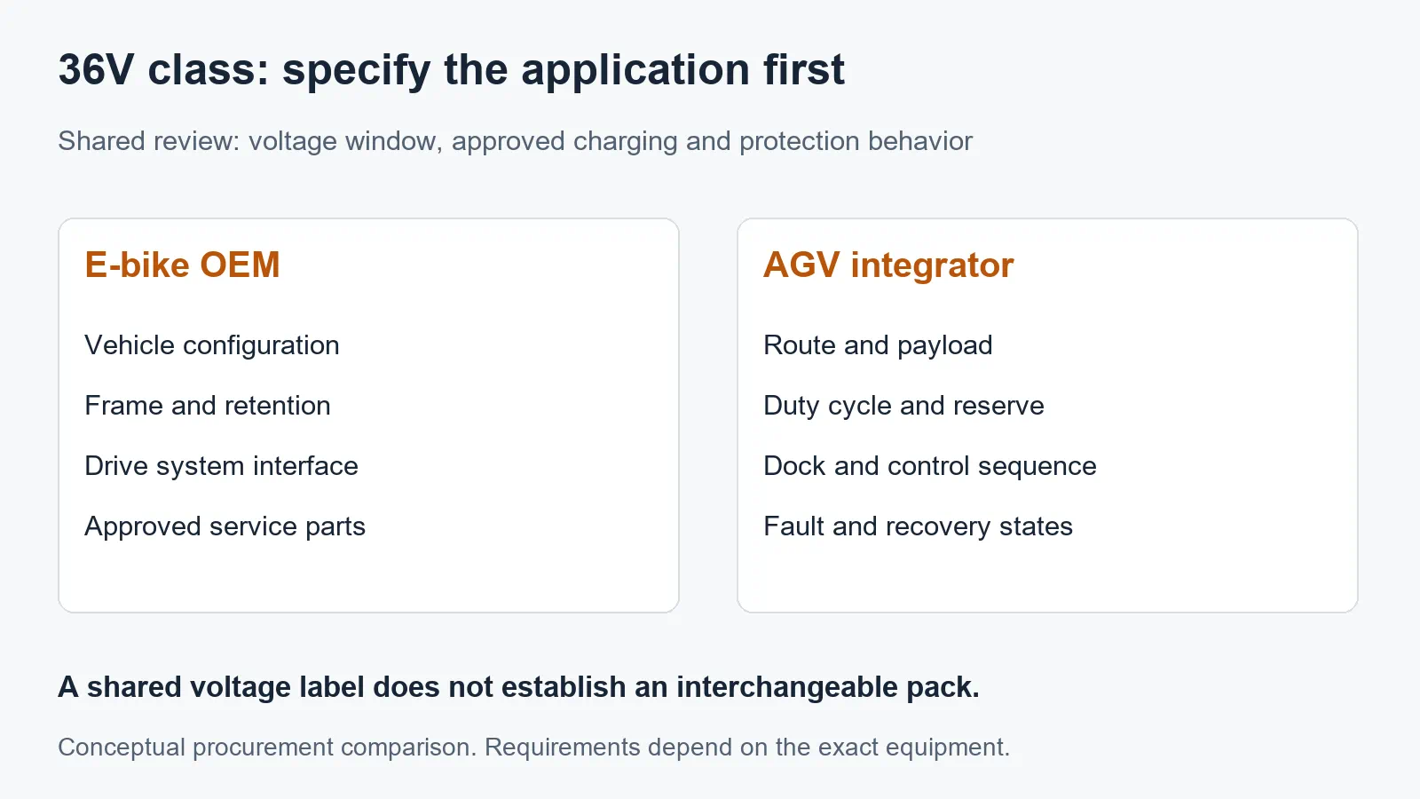
An e-bike inquiry should explain the vehicle platform, mounting arrangement, intended use and approved drive system. An AGV inquiry should explain the route, payload, operating schedule and charging station. Both need electrical compatibility, but the mechanical constraints, service process and evidence of acceptable operation can be substantially different.
| Review topic | E-bike OEM inquiry | AGV integrator inquiry |
|---|---|---|
| Equipment interface | Drive unit, controller revision and permitted battery configuration | Motor drives, onboard loads, controller revision and power distribution |
| Duty profile | Representative assistance demand, starts and route conditions | Loaded travel, acceleration, turns, waits, lifts and auxiliary operation |
| Mechanical fit | Frame or rack envelope, retention, removal access and handling | Compartment access, restraints, connector access and service procedure |
| Charging arrangement | Identified approved charger and battery combination | Identified charger or dock, available charging windows and control sequence |
| Information exchange | Required status indications and any approved system communication | Requested messages, fault handling, wake behavior and controller response |
| Acceptance evidence | Defined vehicle configuration and agreed representative use | Defined route, payload, schedule and agreed operational test |
For e-bikes, capacity must be considered alongside enclosure size, total installed mass and retention. A larger Ah value is not automatically a useful upgrade. Request the drawing, handling requirements and vehicle approval implications before comparing a larger pack. Do not assume that an industrial storage model belongs on a bicycle because its voltage class appears similar.
For AGVs, record the actual operating sequence rather than describing the vehicle only as heavy duty. A vehicle that waits between short trips presents a different energy profile from one that travels continuously while powering auxiliary equipment. Specify which operations must remain available when a low energy warning occurs, and which system controls the return to the charging location.
The industrial battery application range provides a separate starting point for discussing equipment projects. A listed application does not prove compatibility with a particular robot. Share the actual interface documents and identify unresolved requirements on the quotation so that an application name does not become an unsupported performance promise.
Use energy for the operating period and current for the electrical demand at each stage. Ah alone does not answer either question completely. An OEM inquiry should distinguish continuous operation, short events, idle demand and the reserve needed for an orderly stop or return to a charger. State where each measurement was taken.
Consider a hypothetical equipment cycle measured at the battery terminals: 300W for two hours, 80W for one hour and 20W for three hours. The arithmetic energy is 600Wh + 80Wh + 60Wh, or 740Wh. These are invented planning inputs, not measurements from a Mottcell pack, e-bike or AGV. A real project should replace them with representative logged demand.
If a planning exercise assumes that 80% of nominal energy is available to that duty cycle, 740Wh divided by 0.8 gives a nominal energy target of 925Wh. That allowance is an illustration, not an approved depth of discharge. Temperature, ageing allowance, conversion losses and reserve requirements must be handled consistently without counting the same allowance twice.
Check the measurement boundary carefully. Battery terminal measurements already include downstream consumption within that measured circuit. Motor shaft output, controller input and AC charger input describe different points. Applying an arbitrary efficiency percentage to all of them can distort the requirement. Write the boundary beside the number so suppliers can compare like with like.
Current also depends on voltage. An illustrative 720W DC input requires 20A at 36V and 24A at 30V, using current equals power divided by voltage. The 30V value is a hypothetical calculation point, not a permitted discharge limit. The example shows why a current estimate made only at nominal voltage may miss a more demanding part of the operating range.
Capture short events with their duration and repetition. A single peak number without a time basis is difficult to assess. Ask the supplier to evaluate the complete pack, connections and protection configuration against the agreed profile. Do not infer an allowable acceleration pulse from a generic cell rating or a catalogue claim that lacks relevant conditions.
For projects specifically investigating a much larger capacity target, use the separate 36V 314Ah procurement guide. Keep that capacity investigation separate from this application comparison. It does not establish that a 314Ah configuration is available, suitable for an e-bike, or qualified for your AGV duty cycle.
Identify the charger by manufacturer, model and revision, then obtain written confirmation of the intended battery and charger pairing. Include charging voltage behavior, current limits, connection arrangement and any control signals in the review. Matching a connector or a nominal voltage label does not establish an acceptable charging combination.
For e-bike use, the UK government battery safety guidance for e-cycle users recommends genuine replacement batteries and chargers authorised by the e-cycle or drive system manufacturer. An OEM procurement process should preserve that pairing through product changes, spare parts and service documentation rather than treating replacement chargers as interchangeable accessories.
For an AGV dock, describe when charging starts, how connection is detected, how the vehicle is prevented from moving when necessary, and how charging ends. Ask the responsible integrator and supplier to agree on the sequence and failure responses. A contact arrangement that works mechanically still needs an electrical and controls review.
Estimate charging time only after the permitted conditions are known. Dividing required Ah by a proposed current gives a simplified constant current duration. Actual time can also include current taper, temperature restrictions, control delays and the chosen stopping condition. A short break in a production schedule therefore does not prove that the battery can recover all energy used during the preceding shift.
Ask whether the controller can return energy to the battery during braking or another operating mode. If it can, define the expected conditions and have the battery, controller and system designers review them together. Charge acceptance may differ with temperature or state of charge. Do not assume that discharge capability establishes acceptable regenerative charging behavior.
Send the usable compartment dimensions and access opening, not just a desired outer case size. Include mounting features, connector access, cable routing and the intended removal procedure. Confirm whether the supplier drawing includes terminals, covers, handles and other projections. An enclosure that fits the compartment may still be impossible to install or service through its opening.
For an e-bike, document retention and removal access in the actual vehicle configuration. For an AGV, describe the restraint arrangement and service access with the surrounding equipment installed. These details should be reviewed by the responsible design team. Avoid accepting a general statement about rugged construction in place of evidence for the specified mounting and operating environment.
Describe the environment in useful terms: storage and operating temperatures, water or dust exposure, cleaning practice and expected mechanical loading. Request evidence relevant to the proposed enclosure revision. A sealed appearance does not prove an ingress protection rating, and a rating on one enclosure does not automatically cover a different connector, opening or installation.
Agree on a connector drawing and pin assignment covering power and any signal contacts. Include the mating component and its identification in the approved specification. Do not rely on connector colour, shape or a photograph alone. Replacement service instructions should identify the approved parts so later substitutions do not undo the original interface review.
List the information the equipment actually needs: permitted charge or discharge status, relevant warnings, energy status and fault reporting. Then ask which functions the proposed BMS supports. Hardware and software options in a catalogue do not establish that a particular communication protocol, message set or remote function is included in the quotation.
If communication is required, request the interface document, electrical connection details, message definitions and applicable software versions. A shared label such as CAN or RS485 does not establish that two devices understand the same messages. Specify timing, units, scaling and the response to missing or invalid information where these affect equipment operation.
Review wake, sleep and recovery as explicit operating states. An AGV controller may need a predictable startup sequence after a service stop. An e-bike platform may require specific behavior when a removable pack is reinstalled. Ask for the supported sequence and include it in acceptance testing; do not infer it from another battery in the same product family.
Define what the system does when a warning becomes a stop condition. The battery protection function and the equipment control response serve different roles. Qualified engineers should agree on their coordination, including loss of communication or an interrupted charging sequence. Purchasing documents should record the agreed behavior without telling technicians to bypass protection to keep equipment running.
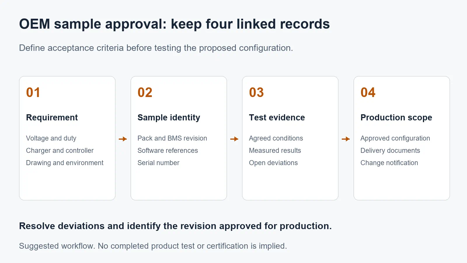
A useful sample order includes the test purpose, identified hardware and software, conditions, acceptance criteria and responsibility for recording results. Establish these items before testing begins. Otherwise, two teams may observe the same behavior and disagree about whether the sample meets the requirement because they used different assumptions.
| Acceptance record | Define before testing | Retain with the result |
|---|---|---|
| Configuration identity | Pack, cell, BMS, enclosure and software references | Sample serial number, label images and approved revisions |
| Electrical interface | Controller and charger combination, operating boundaries | Equipment settings, agreed conditions and measured behavior |
| Representative duty | Route or load sequence, payload, environment and reserve | Time based demand record, delivered energy and stopping condition |
| Charging sequence | Approved pairing, starting condition and completion criteria | Charging record, interruptions and observed control responses |
| Mechanical installation | Drawing, retention, clearances and service access | Installation review, deviations and responsible approval |
| Fault and communication review | Agreed non-destructive test plan and expected responses | Logs, unresolved items and approval or required changes |
Use an agreed representative duty test before claiming a range or shift duration. Record the starting condition, ambient conditions, payload or assistance setting, operating sequence and stopping rule. A favourable result under one route or load does not establish performance for every customer installation. State what the test actually demonstrates.
Keep electrical protection and abnormal condition testing within an approved procedure conducted by qualified personnel or an appropriate laboratory. Do not improvise short circuit, overcharge or mechanical abuse tests in a workshop. The purchasing requirement is to obtain applicable evidence and a reviewable result, not to turn an inquiry checklist into unsafe test instructions.
Close deviations explicitly. A sample may demonstrate useful behavior while still having an open connector, fit or software issue. Record the proposed correction and whether it requires another test. Agree on which approved sample reference production must follow, so a later enclosure or BMS change does not silently replace the configuration that was evaluated.
Ask for documents that identify the actual model and intended application. A company certificate, a cell report and a complete equipment assessment serve different purposes. Match document numbers, model coverage, issuing organisation and configuration details to the offer. Request clarification when the model naming or revision differs rather than assuming the documents are equivalent.
For e-bikes, UL Solutions describes UL 2849 as an assessment of electrical drive train, battery and charger system combinations. A battery statement by itself therefore does not establish certification of the proposed e-bike electrical system. This guide does not claim that SMG36100 or a custom Mottcell configuration holds that certification.
For an AGV, have the responsible integrator identify the requirements applicable to the intended machine, installation and destination market. An e-bike document cannot simply be transferred to an industrial vehicle. Keep required evidence and responsibility for any additional assessment visible in the quotation, sample approval and delivery documentation.
Ask how component identity and configuration changes are controlled between sample approval and production. The cell product information can help frame a discussion of the proposed cell family, but a size or chemistry category is insufficient as the production identity. Obtain the precise reference and an agreed change notification process.
Prepare one requirement package with the equipment description, intended market, voltage window, measured duty profile, reserve requirement, charging arrangement and installation drawing. Add the required status signals, proposed acceptance plan and expected procurement volume. Mark missing information as open items so the initial quotation does not conceal assumptions about application compatibility.
Ask the supplier to separate confirmed catalogue facts, proposed custom features and work that remains subject to engineering review. This makes competing offers easier to compare. Evaluate whether the stated scope includes a sample, interface documents, test evidence and change control rather than comparing only a headline Ah value and an initial price.
Once those inputs are ready, use the Mottcell project inquiry page to request a configuration review. Include your controller and charger references alongside the target capacity. The useful next step is an identified proposal with written open items and an agreed sample plan, followed by an equipment specific acceptance decision.
No. Confirm the vehicle manufacturer approved configuration, voltage window, charger pairing, mounting, connector and any required communication. A similar voltage label or a physically matching plug does not establish compatibility. Use the approved battery and charger combination for the specific platform.
Start with measured energy across a representative operating cycle, then define reserve and applicable operating conditions. Convert the resulting nominal energy target to Ah using the proposed nominal voltage. Review continuous and short event current separately; capacity alone does not establish load capability or charging suitability.
No. The public energy storage table lists 100Ah, 3,840Wh, a 12S BMS configuration and enclosure dimensions. Those are useful catalogue references. Suitability for a specific e-bike or AGV requires the current controlled specification, interface review and relevant application evidence before approval.
10kWh HESS Backup Loads: Circuit Commissioning Guide
12.8V 200Ah Battery Pack Factory: OEM Sourcing Guide
12V 200Ah Battery Pack: Solar Charge Controller Guide
Top 18500 Lithium-Ion Battery Manufacturer (Guide)
15kWh HESS for Solar Systems: AC vs DC Coupling Guide
12V LiFePO4 Battery Capacity Guide: Ah, Wh and Runtime
12V 300Ah Battery Pack: Series vs Parallel OEM Guide
12V 50Ah LiFePO4 Battery Pack: Size, Runtime & OEM Guide
Established in 2005
In 2009, it was awarded the title of "National High tech Enterprise"
 zoe@mottcell.net
WhatsApp: 8617388790296
Fax: 86-0755-84042963
Skype: live:b0ebaecbb8782516
WeChat: +8613428749632

 VR show

 CN
 Home >


